MOCs
- Overview
- Tips and Tricks
- Console Into Cisco Device
- Config
- Interfaces
- VLANs
- DHCP
- NAT
- OSPF
- BGP
- IPSEC Site-to-Site VPN
- Access-Lists
- IPv6
- SSH
Overview
Documentation
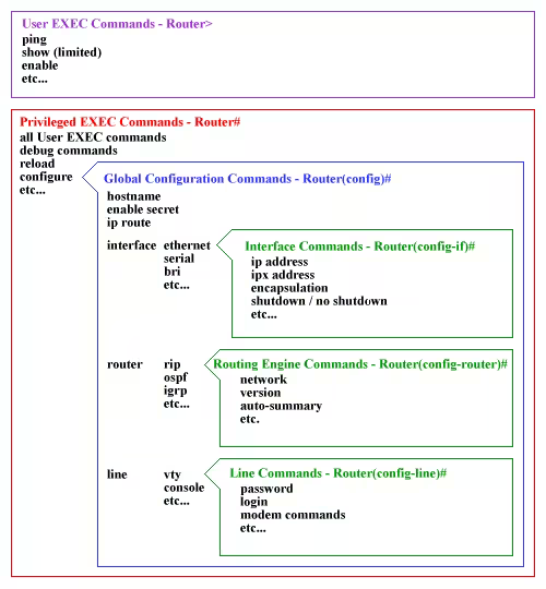
EXEC Modes
- If terminal reads
Router>typeenableto enterRouter#- Under
Router>you’re allowed to doping, show, enable, etc...
- Under
- If terminal reads
Router#typeconfigto enterRouter(config)#- Under
Router#you’re allowed to doall User EXEC Commands, debug commands, reload, configure(config), etc...
- Under
- If terminal reads
Router(config)#view the Official Guide because config branches into 3 different sections.- Under
Router(config)#you’re allowed to dohostname, enable secret, ip route, interface (ethernet, serial, bri, etc...), router (rip, ospf, igrp, etc...), line (vty, console, etc...)
- Under
- Official Cisco Guide (Below is image and table included on the website)
| EXEC Mode | Decription |
|---|---|
| Router> | User EXEC mode |
| Router# | Privileged EXEC mode |
| Router(config)# | Configuration mode (notice the # sign indicates this is accessible only at privileged EXEC mode) |
| Router(config-if)# | Interface level within configuration mode |
| Router(config-router)# | Routing engine level within configuration mode |
| Router(config-line)# | Line level (vty, tty, async) within configuration mode |
Tips and Tricks
Make Script from Command List
If you’re given a command list of
Router>enable
Router#configure terminal
Router(config)#hostname R0
R0(config)#interface fastethernet 0/0
R0(config-if)#ip address 30.0.0.1 255.0.0.0
R0(config-if)#no shutdown
R0(config-if)#exit
R0(config)#interface serial 0/0/0
R0(config-if)#ip address 20.0.0.1 255.0.0.0
R0(config-if)#clock rate 64000
R0(config-if)#bandwidth 64
R0(config-if)#no shutdown
R0(config-if)#exit
Use cyberchef with Find / Replace to remove the EXEC mode
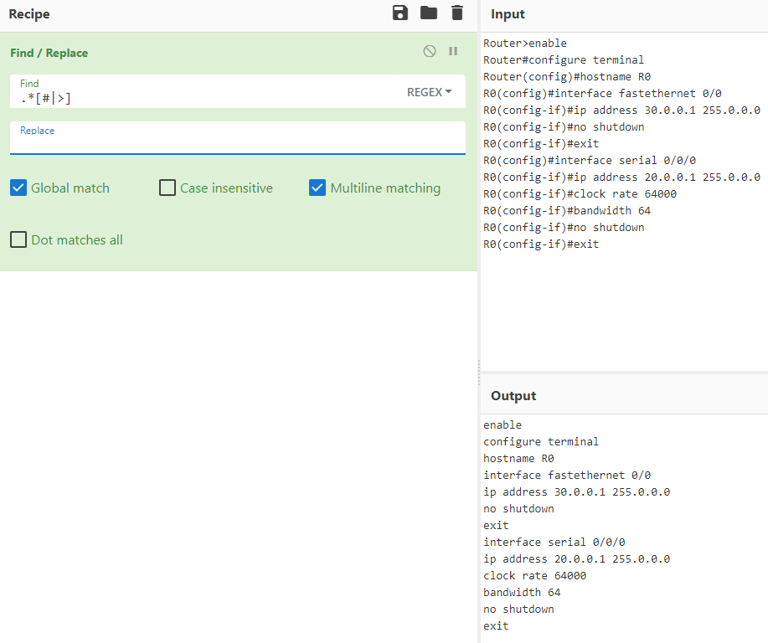
What is happening here is
.* is a wildcard
| means or
[] denotes a character class
This means remove anything that comes before a # or > and replace it with nothing.
.*[#|>]
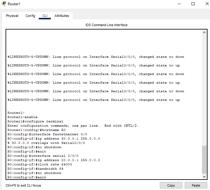
Now in packet tracer copy all of the output code and click paste. This will run all of the code line by line.
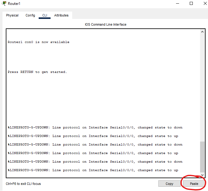
I had run this before so I get the overlap output
Console Into Cisco Device
Steps to Setup Computer
- After connection to the console port open
Device Manager- Take now of the COM<Num> is. This will be used later in the PuTTY config
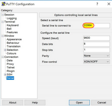
- You want the setting to be the same as the table below
| Variable | Value |
|---|---|
| Bits per sec | 9600 |
| Data bits | 8 |
| Parity | None |
| Stop bits | 1 |
| Flow Control | None |
-
Now open PuTTY and navigator to
SerialunderSSH
-
Now under Session Select the COM<Num> from earlier
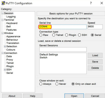
-
Click
Openand if everything was setup properly you should be in the CISCO CLI
Config
CISCO Steps to clear config
- Say
noif prompted to run setup wizard - Enter privileged mode
enable - Enter the command
write erase, which erases the NVRAM file system and removes all files. - At the prompt, confirm that you want to erase all files.
- Enter command
reload, and enternowhen prompted whether to save the configuration. (Otherwise, the switch will reload the current running configuration.) - Confirm that you want to reload the switch, and your switch configuration is almost clean.
- Upon reboot, say
noif prompted to run setup wizard
router>enable
router#write erase
router#reload
Running Config Save
Fully written out
switch#copy running-config startup-config
Short version
switch#copy run start
Interfaces
Configure Ports
To configure one port
Switch(config)#interface range FastEthernet 0/{port}
Allows you to control a range of interfaces from the start to stop port
Switch(config)#interface range FastEthernet 0/{start port}-{stop port}
Port State
VLANs
Description
Virtual Local Area Network
Description
A virtual LAN (VLAN) is a logical overlay network that groups together a subset of devices that share a physical LAN, isolating the traffic for each group. A LAN is a group of computers or other devices in the same place — e.g., the same building or campus — that share the same physical network.
VLANs operate at Layer 3 Source
Create VLANs
Switch(config)# vlan {number}
Switch(config-vlan)# name {name}
Set Access and Trunk Ports
For this to work you must select an interface using
Switch(config)# interface range FastEthernet 0/{port}
For an individual port type
Switch(config-if)# switchport 'access or trunk' vlan {port}
Configure interfaces in “ranges”
Switch(config)# interface range FastEthernet 0/{start port}-{stop port}
Assigning VLAN IP
Router(config)# interface vlan <vlan-id>
Router(config-if)# ip address <ip-address> <subnet>
VLAN State
This will make sure the vlan is in the up state. For the love of all make sure that you do this to vlan 1!
Router(config)#interface vlan {vlan-id}
Router(config-if)#no shutdown
DHCP
Description
Dynamic Host Configuration Protocol
How to create pools

- First select
Servicestab - Then select
DHCPon the right side - Next type in the information you want
- Finally Saving and Adding a. If new Pool select
Addb. If editing Pool selectSave
Working with serverPool
The Pool creates the DHCP limitations for specific subnets
serverPoolis the Default Pool and cannot be removed- In this lab we used
serverPoolforVLAN 1 Management - In the photo shown above once you edit
serverPoolselectSavebecause it’s already been made
Assigning IP Helper Addresses
IP helpers allow computers on different VLANs to be able to access the DHCP Server
- Enter the
CLIfor a MLS - Enter
configmode and type
router(config)# interface vlan {VLAN-ID}
- Then type
router(config-if)# ip helper-address {IPaddr-DHCP-Server}
- Finally type
exit
- Repeat steps 2 to 4 for the rest of the VLANs
NAT
Description
Network Address Translation
Types of NAT
Static
Base Setup:
enable
conf t
interface {interface} {interface_#}
ip nat inside
exit
interface {interface} {{interface_#}
ip nat outside
exit
ip nat inside source static {source_ip} {static_ip}
Example:
enable
conf t
interface fastEthernet 0/0
ip nat inside
exit
interface serial 0/0/0
ip nat outside
exit
ip nat inside source static 10.0.0.2 50.0.0.1
PAT
Description
Port Address Translation
Base Setup:
enable
conf t
interface {interface} {interface_#}
ip nat inside
exit
interface {interface} {{interface_#}
ip nat outside
exit
ip nat pool {pool_name} {start_ip} {stop_ip} netmask {subnet_mask}
access-list 1 permit {internal_network_address} {wildcard_subnet}
ip nat inside source list 1 pool {pool_name} overload
Example:
enable
conf t
interface fastEthernet 0/0
ip nat inside
exit
interface serial 0/0/0
ip nat outside
exit
ip nat pool test 30.0.0.120 30.0.0.120 netmask 255.0.0.0
access-list 1 permit 192.168.0.0 0.0.0.255
ip nat inside source list 1 pool test overload
Notes:
To show active nat stats
enable
show ip nat statistics
OSPF
Description
Open Shortest Path First
Base Setup
enable
config t
interface {interface} {interface_#}
no shutdown
ip address {ip_address} {subnet}
router ospf 1
network {network_address} {wildcard} area {area_#}
Example:
enable
config t
interface GigabitEthernet 0/0
no shutdown
ip address 10.8.1.1 255.255.255.248
router ospf 1
network 10.8.1.0 0.0.0.7 area 0
Add Authentication
MD5:
Base Setup:
enable
config t
interface {interface} {interface #}
ip ospf message-digest-key {instance #} md5 {password}
ip ospf authentication message-digest
Example:
enable
config t
interface GigabitEthernet 0/0
ip ospf message-digest-key 1 md5 testing
ip ospf authentication message-digest
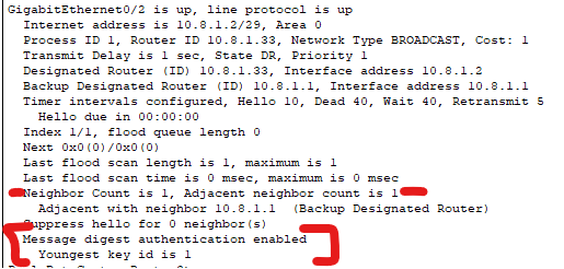
Verification:
enable
show ip ospf interface fastEthernet 0/0
Output:
SHA-512:
Base Setup:
enable
config t
key chain {key_name}
key {#}
cryptographic-algorithm {algorithm}
key-string {password}
exit
interface {interface} {interface_#}
ip ospf authentication key-chain {key_name}
Example:
enable
config t
key chain R2
key 1
cryptographic-algorithm hmac-sha-512
key-string testing
exit
interface GigabitEthernet 0/1
ip ospf authentication key-chain R2
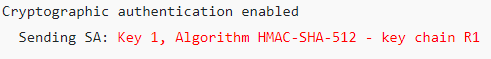
Verification:
enable
show ip ospf interface GigabitEthernet 0/1 | begin auth
Output:
BGP
Description
Border Gateway Protocol
Base Setup:
enable
config t
interface {interface} {interface_#}
no shutdown
ip address {ip_address} {subnet_mask}
router bgp {as_#}
neighbor {neighbor_ip} remote-as {neighbor_as}
network {network} mask {subnet_mask}
Example
enable
config t
interface GigabitEthernet 0/0
no shutdown
ip address 10.8.1.1 255.255.255.248
router bgp 1010
neighbor 192.168.2.2 remote-as 3033
network 192.168.1.0 mask 255.255.255.252
Notes:
For the line only 1 of the routers has to advertise the network. AS WELL INTERNET NETWORKS NEED TO BE ADVERTISED!
network 192.168.1.0 mask 255.255.255.252
IPSEC Site-to-Site VPN
Description
Internet Protocol Security
Base Setup:
The {access_list_#} must be greater than 100
! Identify traffic to send through tunnel with access-list
access-list {access_list_#} permit ip {src_net} {src_mask_wildcard} {dst_net} {dst_mask_wildcard}
! Configure IKE Phase 1 ISAKMP Policy on Router
crypto isakmp policy 10
encryption aes 256
authentication pre-share
group 5
exit
crypto isakmp key {KEY} address {public_ip_of_other_router}
! Configure the IKE Phase 2 IPsec policy
!- Create the transform-set "VPN-SET"
crypto ipsec transform-set VPN-SET esp-aes esp-sha-hmac
!- Create the crypto map "VPN-MAP"
crypto map VPN-MAP 10 ipsec-isakmp
description VPN connection to {peer_router_name}
set peer {public_ip_of_other_router}
set transform-set VPN-SET
match address {access_list_#}
exit
! Configure the "crypto map" on the outgoing interface.
interface {interface} {interface_#}
crypto map VPN-MAP
Example:
! Identify traffic to send through tunnel with access-list
access-list 101 permit ip 172.16.84.0 0.0.0.255 192.168.25.0 0.0.0.255
! Configure IKE Phase 1 ISAKMP Policy on Champlain Router
crypto isakmp policy 10
encryption aes 256
authentication pre-share
group 5
exit
crypto isakmp key NET330 address 140.230.18.2
! Configure the IKE Phase 2 IPsec policy
!- Create the transform-set "VPN-SET"
crypto ipsec transform-set VPN-SET esp-aes esp-sha-hmac
!- Create the crypto map "VPN-MAP"
crypto map VPN-MAP 10 ipsec-isakmp
description VPN connection to Middlebury
set peer 140.230.18.2
set transform-set VPN-SET
match address 101
exit
! Configure the "crypto map" on the outgoing interface.
interface FastEthernet 0/0
crypto map VPN-MAP
Notes:
To see if the VPN is working:
enable
show crypto ipsec sa
Access-Lists
Base Setup:
Standard
enable
config t
ip access-list standard {list name}
! To deny network and allow everything else
deny {network address} {wildcard subnet}
permit any
! To permit network and deny everything else
permit {network address} {wildcard subnet}
! This works becuase of the hidden deny any any
exit
! Below is to apply list to interface
interface {interface} {interface #}
ip access-group {list name} {in or out}
Extended
enable
config t
ip access-list extended {list name}
! To deny ip from the network to specified host and allow ip for everything else
deny ip {network address} {wildcard subnet} host {host ip}
permit ip any any
! To permit only www (website) traffic to specifed machine and deny everything else
permit tcp any host {host ip} eq www
! This works becuase of the hidden deny any any
exit
! Below is to apply list to interface
interface {interface} {interface #}
ip access-group {list name} {in or out}
Example:
Standard
enable
config t
ip access-list standard STND-1
! To deny network and allow everything else
deny 192.168.10.0 0.0.255.255
permit any
! To permit network and deny everything else
permit 192.168.1.0 0.0.255.255
! This works becuase of the hidden deny any any
exit
! Below is to apply list to interface
interface serial 0/0/0
ip access-group STND-1 in
Extended
enable
config t
ip access-list extended EXTEND-1
! To deny ip from the network to specified host and allow ip for everything else
deny ip 200.200.200.0 0.0.0.3 host 192.168.20.210
permit ip any any
! To permit only www (website) traffic to specifed machine and deny everything else
permit tcp any host 192.168.20.201 eq www
! This works becuase of the hidden deny any any
exit
! Below is to apply list to interface
interface FastEthernet 0/0
ip access-group EXTEND-1 out
IPv6
Base Setup:
enable
config t
ipv6 general-prefix {prefix name} {prefix}
interface {interface} {interface #}
no shutdown
ipv6 address {ipv6 address}
ipv6 unicast-routing
interface {interface} {interface #}
ipv6 rip process1 enable
interface {interface} {interface #}
ipv6 address autoconfig
no shutdown
ipv6 rip process1 enable
Examples:
enable
config t
ipv6 general-prefix champ-pre 2620:E4:C000::/64
interface FastEthernet 0/1
no shutdown
ipv6 address 2620:E4:C000::1/64
ipv6 unicast-routing
interface FastEthernet 0/1
ipv6 rip process1 enable
interface FastEthernet 0/0
ipv6 address autoconfig
no shutdown
ipv6 rip process1 enable
Notes
! For eui-64
enable
config t
ipv6 general-prefix {prefix name} {prefix}
interface {interface} {interface #}
no shutdown
ipv6 address {ipv6 address} eui-64
ipv6 unicast-routing
interface {interface} {interface #}
ipv6 rip process1 enable
interface {interface} {interface #}
ipv6 address autoconfig
no shutdown
ipv6 rip process1 enable
SSH
Enable SSH:
enable
config t
hostname {hostname}
aaa new-model
username {username} password 0 {password}
ip domain-name {domain}
crypto key generate rsa
ip ssh time-out 60
ip ssh authentication-retries 2
line vty 0 4
transport input ssh